Reinventing the 3D Wheel
2014-08-12 23:00
This is an explanation of the 3D drawing techniques that have been used on this site. During the life of this site I have implemented and re-implemented linear algebra libraries and 3D demos which used them.
Here are some demos that make use of 3D:
Doing everything from scratch
When I started writing demos for this site I had an aversion to using any third party libraries. I wanted to learn how everything worked and that meant shunning existing technology in favour of writing everything myself from scratch. Many of the demos on this site are 3D but none make use of WebGL, three.js or any other well established 3D web technology. All the demos use a 2D HTML canvas context, with all the maths to make images appear 3D implemented in javascript.
High School Technical Drawing
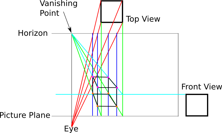
My first attempt at a 3D engine was based very closely on a technique I learnt in my high school graphics class. This class focussed on technical drawing both by hand on paper and using CAD software. We learnt how to do perspective projection on paper in the following way:
Perspective projection I learnt in high school
|
Here’s how to hand draw a wireframe cube using perspective projection as per the diagram above:
Start by drawing lines from each point of the top view to the eye.
From the point where each of these lines crosses the horizon, draw a line straight
down until it intersects the picture plane.
From each point in the top view, draw a line straight down until it intersects the
picture plane, then begin a new line from that point to the vanishing point.
For each point in the top view with a height (position on the up/down axis) of 0,
it's position in the perspective projection is the intersection of its corresponding
green and
blue lines.
For each point in the front view (besides the ones with 0 height), draw a horizontal
line through that point which intersects all
green
lines. From each intersection of a line from a point on the front view with
a
green line from a corresponding point in the top view,
draw a line from the intersection point to the vanishing point.
The intersections of the
cyan lines with
the corresponding
blue lines are the positions
of the corresponding points in the perspective projection.
Now that the points are all present, draw lines between the ones between which edges exist in the shape you’re trying to draw.
Automating the process
As I knew how to draw perspective projections of shapes by hand, the next step was to write a program to draw shapes using the same technique. I actually wrote a QBasic program to do this for flat objects (where all points have 0 height) while in my “experimenting with MS-DOS” phase in high school, and then re-implemented it in javascript for non-flat objects based on the same maths a year or so later.
For a computer to be able to draw perspective projections, it needs a way to compute the 2D coordinates for drawing on the screen, from a given point specified using 3D coordinates. Repeatedly doing this for each point of a 3D object, and drawing lines between the corresponding points on the screen, results in its perspective projection.
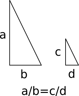
Basic idea of similar triangles
|
So how to convert a 3D point into a 2D point which can be drawn on a screen? My solution used Similar Triangles As shown in the diagram on the left, if you have 2 right-angle triangles with the same ratio of side lengths, and you know the side lengths of one of them, and the length of one of the sides of the other, the length of the remaining side can be derived.
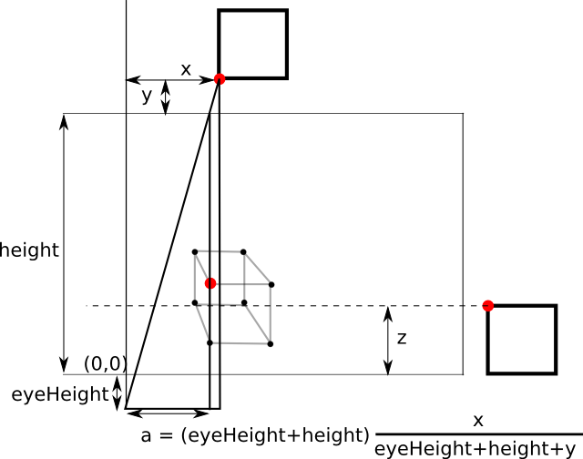
The perspective projection above is full of triangles, so all I needed to do was find some triangles to help compute the 2D point on the perspective projection from the information known about the point.
Below is the triangle used for finding the horizontal point (called ‘a’ in the diagram).
Method for finding the horizontal position of a 2D point in a perspective projection
|
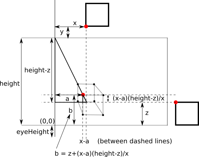
Once the horizontal position of the point is known, it can be used to compute the vertical position (referred to here as ‘b’) in a similar way:
Method for finding the vertical position of a 2D point in a perspective projection
|
Once this formula for converting between 3D and 2D points is implemented, it’s some simple bookkeeping to know which 2D points must be connected to complete the wireframe image. This technique proved suitable for several applications where it wasn’t necessary to ever draw solid polygons or other non-wireframe shapes. Here’s some demos that use it:
The “Proper” Way
In 2012 I took UNSW’s Computer Graphics course with Tim Lambert. Each week I would learn something more about how conventional 3D engines work, and I thought it would be neat to build my own 3D engine (entirely in javascript with no video hardware support) and add features as I learnt about them. Here’s how that engine evolved as the course progressed.
This section has several interactive demos of the engine at various stages of completion. To control the eye’s point of view in the demos, use WASD keys to move forwards, left, backwards and right respectively, and the up, down, left and right arrow keys to move up, down, rotate left and rotate right respectively.
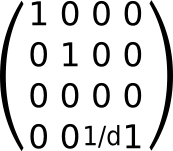
Rather than using a complicated formula to compute the position on screen of a 3D point using perspective projection, one can use matrix multiplication to achieve the same effect. Represent the point (x, y, z) as a vector in R4 (x, y, z, 0) and multiply it by the matrix:
Perspective transform matrix
|
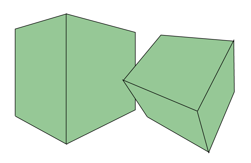
This results in a vector in R4 where the first 2 values are the x and y coordinates on the screen to draw that point. The ‘d’ in that matrix refers to the “depth of field”, or “how rapidly points vanish towards the centre of vision”. This image was rendered using a high depth:
High depth example
|
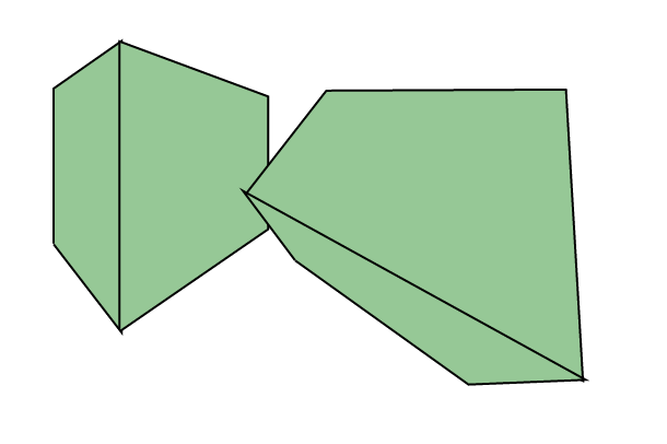
This was rendered using a low depth:
Low depth example
|
Here’s a demo that does a perspective transform and nothing else:
Wireframe
Back-face Culling
For this to make sense we need to add faces to our 3D engine. So far all we have been able to draw were points and lines. Now we need to add solid polygons. Think of this as taking a 3D model made from wire and attaching paper cutouts to it. In the real world paper cutouts have a front and a back and are obviously visible from both sides. When our wireframe is completely covered by cutouts, each cutout will have one side (the inside side) which cannot be seen from outside the object.
Having the faces be visible from both sides means more work for the 3D engine. As faces are flat, only one side of the face can be seen at any point, so if we only draw the visible side we generally halve the number of faces we need to consider at any point. This is the idea behind back face culling. Each face is given a front and back face, where the front face faces the outside of the object. With back-face culling, the backs of faces are not drawn.
Here’s a demo of a cube drawn using back-face culling:
Backface Culling
Note that in the simple cube example above it appears that faces are drawn in the “correct” order, in that things in the foreground obscure the things behind them. Back-face culling is sufficient for correct draw order in convex shapes such as cubes, though is insufficient for more complex examples:
Backface Culling 2 Cubes
Clipping Plane
Using the similar triangles formula or the matrix multiplication, points behind the eye still get assigned points on the screen. In order to not draw points which are behind the eye, we need a way to remove all these points before rendering. Using a clipping plane to “slice” through the 3D model of the world before rendering is one way to do this. This example places the clipping plane in front of the eye so its effect is more visible. Back-face culling is also in use which can be seen when part of the cube is clipped and the inside is not visible.
Clipping Plane
Binary Space Partitioning
A 3D model is generally represented as a list of polygons, each representing a face. To correctly render the model, the faces must be drawn in a specific order so that things in the foreground cover up the things behind them. Thus we need a way to sort faces into a suitable order such that if they are drawn in that order it looks “correct”. This is not as simple as it may seem, as there may exist mutually overlapping faces, such as the bottom of a cardboard box, where every face is obscured by some other face. Thus we can’t just sort the faces as no face could be drawn last and thus there there may be no order in which we can draw the faces.
The solution is to spit some faces so as to remove all mutually overlapping faces, and sort these faces in the correct order. One algorithm which achieves this is “Binary Space Partitioning”. This involves creating a binary tree of faces known as a Binary Space Partition Tree (BSP Tree), where each face has a front and back side. For each face in this tree, all faces in the right subtree are completely in front of the current face, and all faces in the left subtree are completely behind it. For a face A to be completely in front of or behind some other face B, it means that the plane which contains face B does not intersect face A.
Once this tree is created, faces can be drawn in order by traversing the tree in-order (left subtree, then root, then right subtree). The algorithm for inserting a face into a BSP Tree is as follows:
bsp_insert(face, tree):
    if (tree.value == null):
        tree.value = face
    else if (face is entirely in front of tree.value):
        bsp_insert(face, tree.right)
    else if (face is entirely behind tree.value):
        bsp_insert(face, tree.left)
    else:
        face_front = part of face in front of tree.value
        face_behind = part of face behind tree.value
        bsp_insert(face_front, tree.right)
        bsp_insert(face_behind, tree.left)
Depending on the order in which faces are added, the number of split faces may vary. It is ideal to minimize the number of splits and thus to reduce the eventual number of faces making it faster to draw them. Generally the list is shuffled and repeatedly inserted into new trees until a reasonably small tree is found. A BSP Tree need only be generated once ever for a given 3D environment, so for games which use BSP Trees, one is pre-compiled when the game is made and the game comes with all its BSP Trees already computed.
A downside of BSP Trees is that they must be regenerated when anything changes in the environment. This makes them not ideal for rendering moveable characters in games.
Here’s a demo showing how a particular 3D environment is split up by the BSP algorithm.
BSP Wireframe
Here’s the same demo with solid faces:
BSP Demo
And here’s another demo using the same technology to render rooms:
Rooms
Conclusion
I don’t intend to actually ever use this 3D engine for anything practical. In reality, massively parallel video hardware is used to implement Z-Buffering - a technique which can be used in place of BSP, and libraries exist to remove the need to implement all these low level features. These demos really just served as a learning exercise to myself. Reinventing the wheel is a great way to understand how wheels work.


